Master Pattern Development
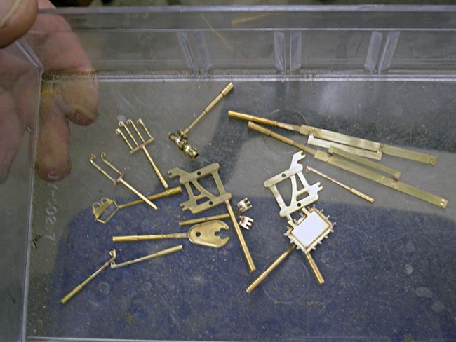
The process of producing highly detailed limited production models has to rely heavily on the development and use of cast parts, usually made from brass and sometimes nickel-silver. In turn, the development of brass parts relies exclusively on the development of master patterns from which the parts to be replicated will ultimately be made. Shown below is a sampling of patterns which have been prepared for the next step in the process which is making molds of the master patterns, this process will be explained further by clicking on the 'Casting' heading located on the Model Construction page. You will notice that the patterns vary greatly in size and complexity, keeping in mind that the straight shafts attached to each pattern is part of the 'treeing' process required for the mold making.
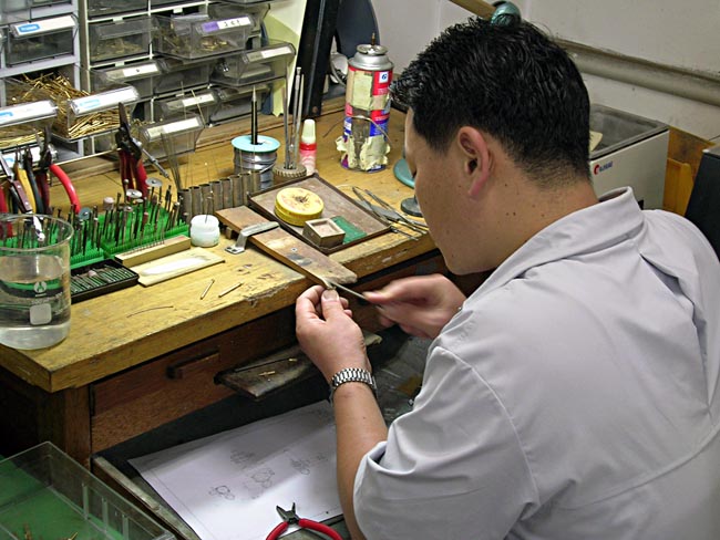
The techniques used for creating patterns has evolved significantly in recent years, but it still requires a skilled craftsman to interpret the design whether it be a CAD file or hand drawing. Further, the craftsman has to either form, machine or fine tune by hand the component pieces of the pattern. The workbench shown is very typical of one used for small pattern hand work. The skill required for pattern making can be closely equated with that of a tool & die maker, relying on hand power as well as power tools. You can see in this photo a small part being hand finished with a file.
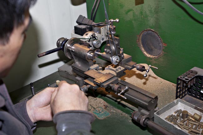
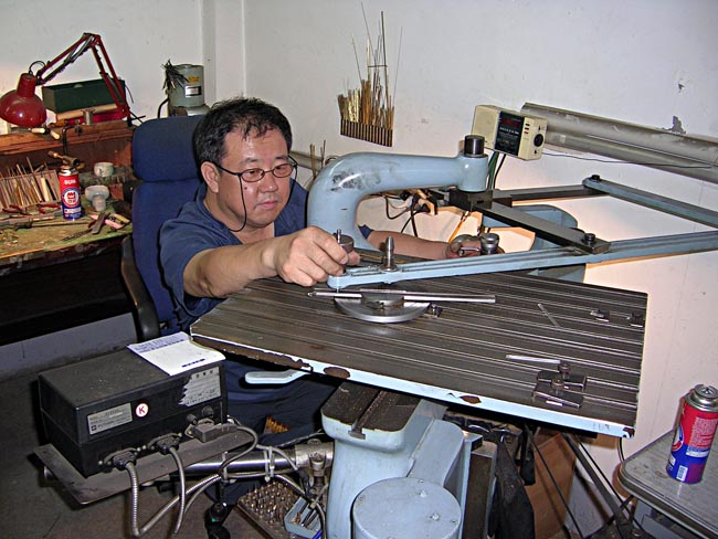
When required, power tools and equipment are brought into play, the craftsman has to know what piece of equipment is best suited for the purpose. In the next photo, Mr. Kim is using a small power combination mill/lathe to machine a small sample part for these photos. Many of the detail parts that must be created are subminiature in size and require special equipment that is capable of handling the very small raw materials required, in this case Mr. Kim built the machine himself.
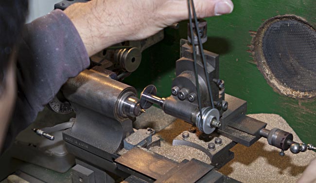
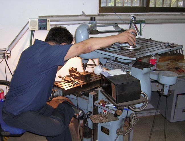
This view provides a closer look at the work being done as Mr. Kim manipulates the controls on the front of the machine. You'll notice that the part being created is so small that you can not even begin to see what it is!
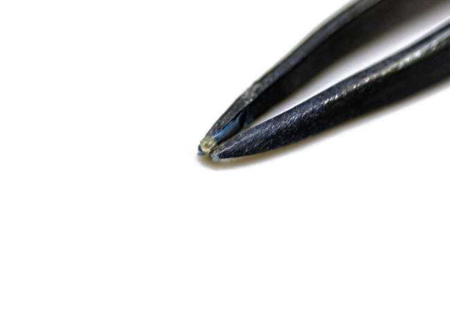
The finished part the Mr. Kim was machining was a tiny hex-head detail that will be applied to another component to simulate fastener detail on a pattern assembly. The hex-head is being held in a fine tipped pair of tweezers. This process has to be repeated over and over again to complete the patterns for a typical model project.
There is a wide variety of power equipment that is typically used for pattern making. Mr. Lee is shown below operating a pantograph machine that is used for milling raw material to predetermined shapes. The unique nature of this machine is that it can 'trace' pre made patterns in variable duplication ratios by adjusting the interlinked arms that you see on the working surface of the machine table. I have watched these machines being used since my first visit to Korea more than twenty years ago and I am still amazed by what Mr. Lee can accomplish using it!
Another view of the same machine, you can get a better idea of how it actually functions. The tracing table is the upper surface and the actual cutting head is where Mr. Lee's attention is focused. This machine requires the ultimate in hand and eye coordination.
As model builders have looked for more production in a shorter period and also greater precision, CNC machining centers have been introduced into the process. Mr. Lee is unique in that he has a machining center in his own factory which is very unusual due to the cost. While this technology does reduce the amount of hand labor, the equipment must be programmed based on a 3D CAD design file that must be drawn up by a skilled CAD operator. To some degree, automated machines are also being relied on to augment the diminishing number of skilled pattern makers. Unfortunately, it's becoming easier to find competent CAD operators than it is skilled trades people, but it is not necessarily less expensive. The problem is only partially solved by the machines, because often times it requires the background experience of a pattern maker to have the parts turn out as required, despite the capabilities of the machines.
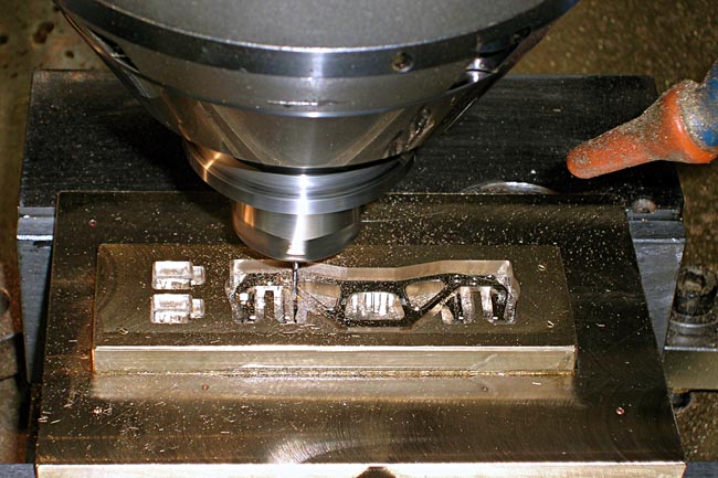
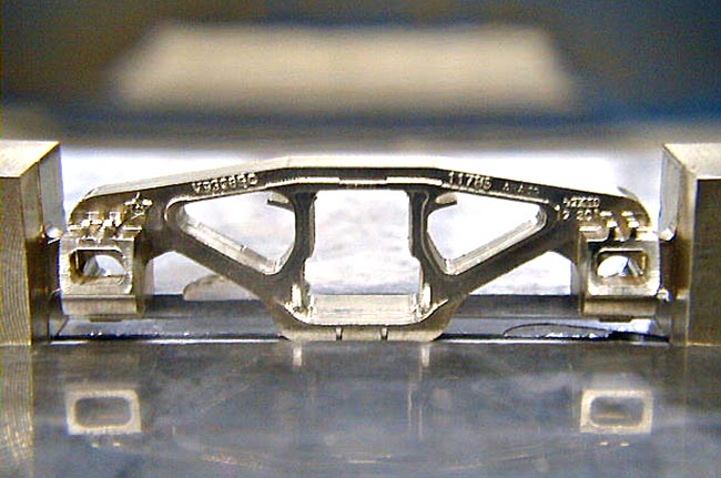
This next photo provides a closup view of the cutting head turning a solid block of brass into a tender truck side frame.
The next photo shows another truck with the machining complete. The ends have to be 'dressed' off and some fine tuning with a file done, but the basic side frame is complete. Notice that even the raised lettering was machined in place.
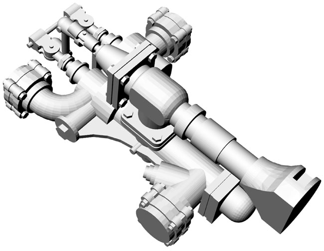
As the shortage of skilled workers intensifies, the search continues for alternatives. I have been following the technology common referred to as 'Rapid Prototyping' for almost ten years now. Only in the last year or so has this technology developed to the point where it showed promise for use in developing O scale models. With this new technology you start with a completed 3D design much the same as that used for programming a CNC machining center. A rendering of such a design file is shown below, it represents in exacting detail what the printing machine will see as it reads the numeric input which is created by the translation process from the drawing file. There are factors to be considered and allowances to be made based on how the machine functions, that is part of the 'magic' of making the output match the intended design.
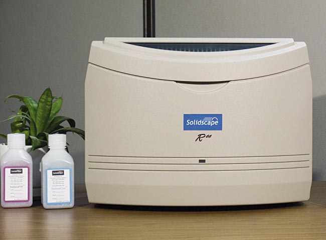
Shown in the next photo is the actual 3D printer that creates the resin master pattern from which the molds will be made just as would be done from the machined metal patterns. The unit is not much larger than a typical laser printer that you would find in your office or home, but it is substanially more expensive, approximately $40,000 for the basic equipment to get started.
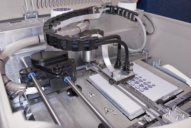
This interior view of the 3D printer shows the surface where the spray nozzles deposit the melted resin on the precision machined baseplate in precisely measured amounts in very precise locations.
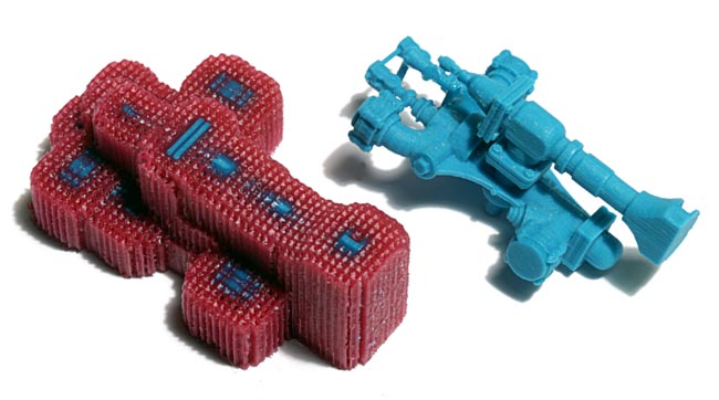
You may recognize the part below as an injector assembly from a steam locomotive. The process of the machine creating this resin part can take a number of hours depending on the desired finished resolution. To explain a little more about what you are actually looking at, the structure on the left is the completed part as it comes out of the machine. The red resin is a support structure that helps to hold the fine detail of the blue part in place until the run is completed. Once the run is complete, the entire structure is placed in a special solution that desolves the red support structure and leaves behind only the blue finished resin part. This explanation is greatly simplified, leaving out a number of time consuming steps, to make it easier to understand.
Regardless of what method is used, the goal is a finely finished part that is suitable for making a mold for use in the next step of the casting production process. There is no way to eliminate the need for skilled craftsmen, the only hope is to supplement their capability to make greater production possible with fewer hands involved in the process. Unfortunately, the cost of labor is replaced by the very substantial cost of equipment, so the effort does not get less expensive with time. I hope that this general overview has provided a bit of insight regarding some of the techniques used in this phase of the production. Keep in mind that this process has to be repeated hundreds of times in the course of producing one O scale locomotive project.
Copyright © 1997- 2024 Kohs & Company Inc, All Rights Reserved
MODEL CONSTRUCTION